XBotBlock
XBotBlock Concepts
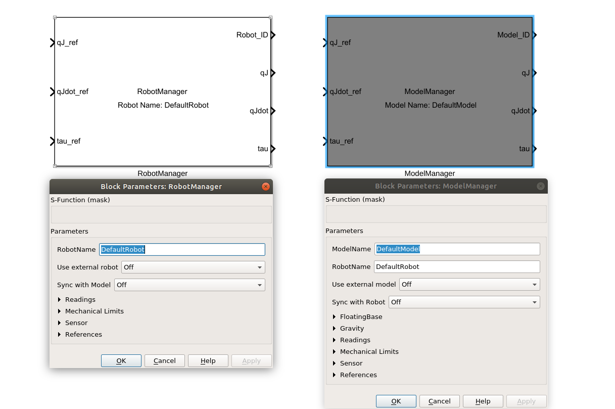
Robot and Model Managers: Robot or model manager is responsible to create a robot or model interface, handling it (sense, update, move and synchronization) and its information (readings, references, mechanical limits, floating base, gravity, sensors and etc.).
Robot and Model Name Maps Mechanism: This mechanism allow to the robot manager and model manager to save into maps the robot and model interfaces using the names.
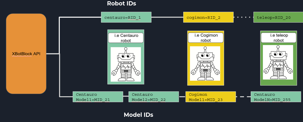
Robot and Model IDs Mechanism: When a robot or model interface is saved into a map, an robot or model ID is created, this allow to connect other blocks with a specific robot/model interface.
Control system diagram: This concept allows the user to develop the control strategy using the control system engineering way.
Block Diagram Programming: The main scope of this toolbox is to develop Non real time (NRT) and real time (RT) control strategy using the block language.
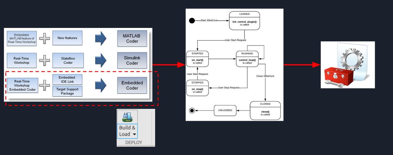
Model,Software,Process and Hardware in the Loop testing: Using these approaches it’s possible to test/debug easily the model developed, reducing the time to plot, save and calibrate the data of it. Furthermore with the auto-code generation process it’s possible to get NRT and RT code using it inside xbotcore toolchain.
Robot and Model Managers
The robot or model manager is a mandatory block that every simulink model shall use in order to create a robot or model interface. After this, the user can select all functions of XBotInterface where a robot and model can access to, described into background page. For a model was added the floating base and gravity functions where it’s possible to reconfigure it with new values.
Robot and Model Name Maps Mechanism
There are two ways to get a robot/model interfaces and fill the robot/model interface maps:
ROS: The managers will try to find on ROS network the XBotCore node that will provide the parameters to create a robot and model interface.
XBotCore RT plugin: Thi approach is used when the user wants to create a Real Time code. This means that since you’re developing code for xbotcore in RT, an internal robot and model interface shall be saved inside the maps. Then the code will have the maps filled in a proper way to cover the model working, codified by auto code generation toolbox (Embedded Coder).
When a robot/model interface is created, this is saved into the map using the name specified into the robot/model manager mask.
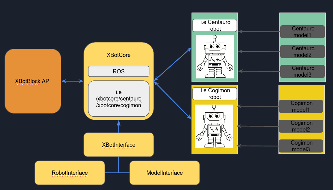
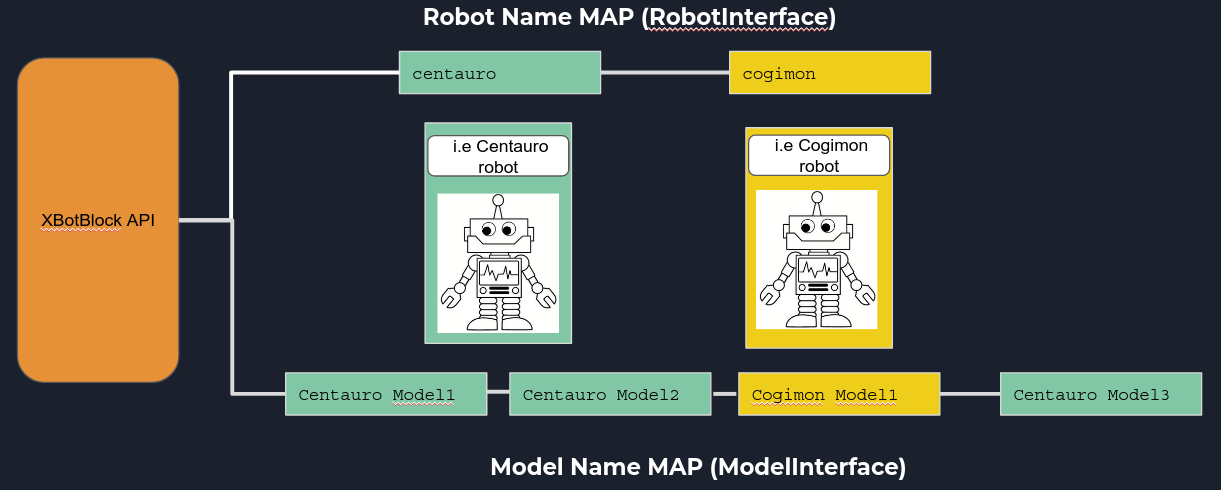
NOTE: DefaultRobot name means ROS namespace equal to /xbotcore specifying that xbotcore is handling a single standard robot where it’s not necessary to specify the robot name (i.e centauro, cogimon etc.)
Robot and Model IDs Mechanism
When a robot or model manager is created, a robot ID or Model ID is generated. The IDs are both UINT8, then it’s possible to create 0-255 robots and 0-255 models. In order to distinguish robots from models, a division was done making it possible to create 1-20 robots and 21-255 models.
Note: Robot ID or Model ID equal to zero is not valid.
Control System Diagram
As you noticed from the robot and model managers session, one single block of manager can get/set all information related on robot and model. This approach corresponds to the most control system diagrams:
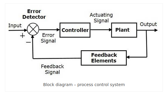
Where the plant model is the robot (model) manager.
The feedback signal are read and refresh by sense (robot) and update (model) operations.
The actuating signal are write by move (robot) and update (model) operations.
The controller is a NRT or RT code.
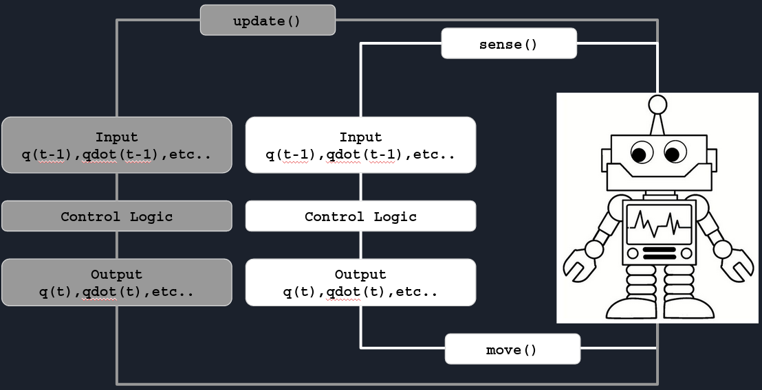
It’s possible to synchronized a model with a robot:
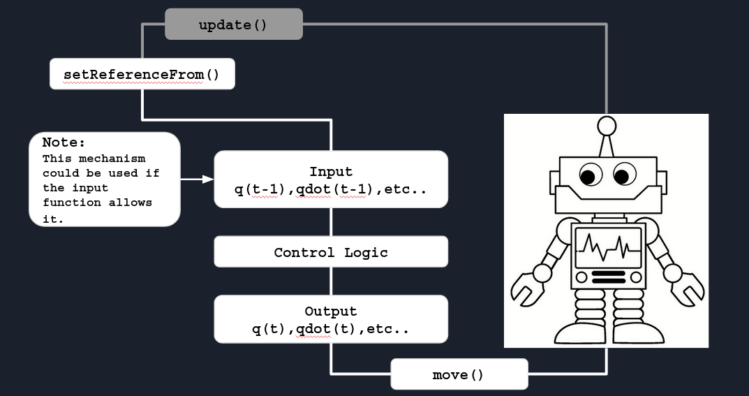
It’s possible to synchronized a robot with a model:
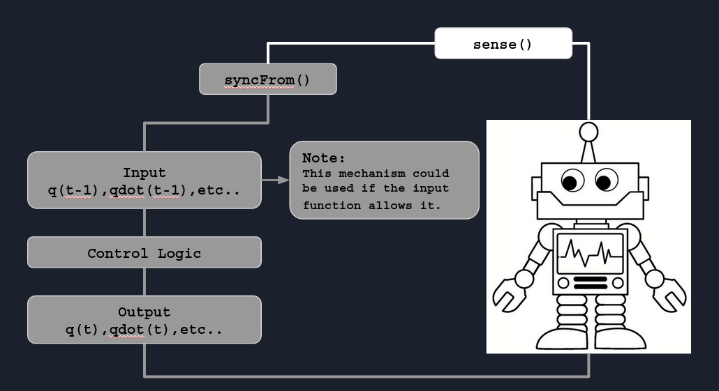
Example:
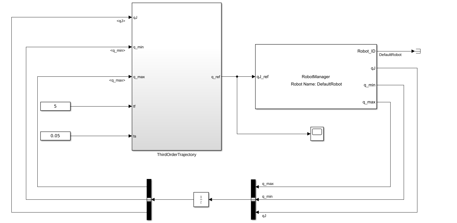
NOTE: The user can split in two parts the plant model, robot or model manager, having only the input part to read the information and the output part, exploiting the external robot or model ID or name map concepts, to actuate. In particular, for all utility blocks such as (Jacobian, Kinematics, Dynamics and Sensors), it’s possible to use only the external ID mechanism.
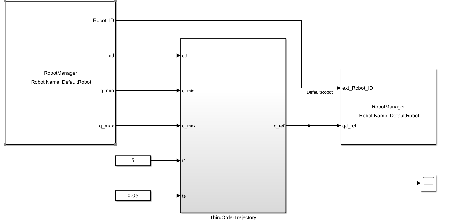
Block Diagram Programming
As expressed the block language has a different way to develop algorithms from classic C++/Python language. The blocks can help to design the control strategy (law) quickly where instead with classical language the user needs time to create the program infrastructure before developing the main core of code. Matlab/Simulink helps the user of its development and translating the XBotInterface API’s it’s possible to speed up the design phase.
As you noticed the blocks shown before have a color code that described the difference between a robot (white) and a model (gray).


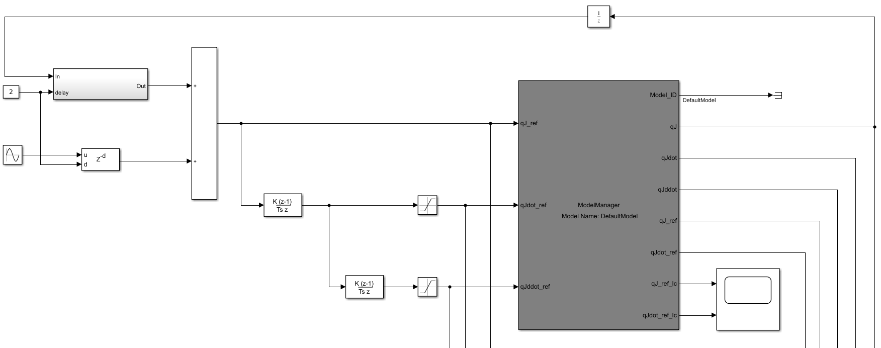
Model,Software,Process and Hardware in the Loop testing
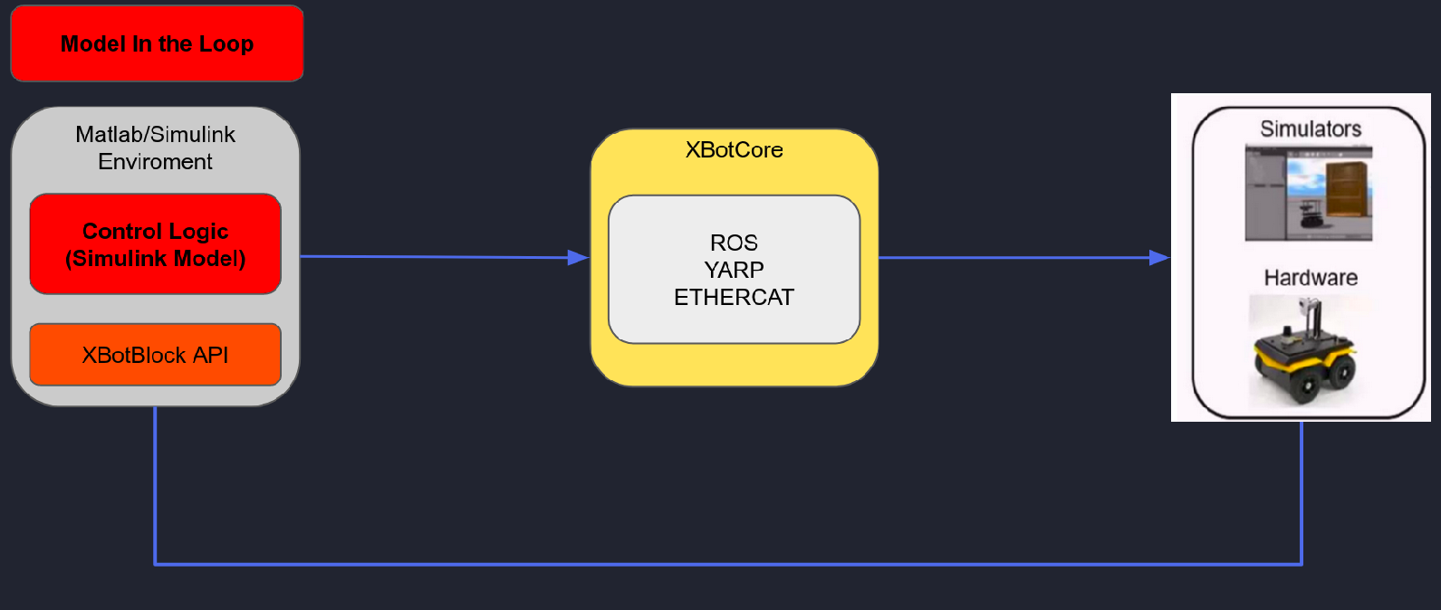
The model in the loop testing is a type of test where the user simply run the simulink model, verifying the behaviour of the control strategy in a simulation environment like RViz or Gazebo.
Note: during the simulation since the Matlab/Simulink GUI and model simulated use the same resources when a scope, constant or other blocks are opened, the ROS communication with XBotCore can have problems. For this reason it’s better to use this testing type only in simulation environment.
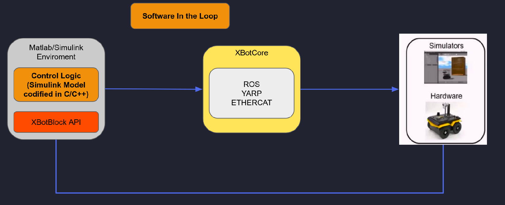
The software in the loop testing is a type of test where the user simply run the simulink model but all blocks are codified in code language (C, C++ or Python), verifying the behaviour of the control strategy in a simulation environment like RViz or Gazebo.
Note: during the simulation since the Matlab/Simulink GUI and model simulated use the same resources when a scope, constant or other blocks are opened, the ROS communication with XBotCore can have problems. For this reason it’s better to use this testing type only in simulation environment.
This type of test needs an external tool box that is not available into Matlab IIT campus license.
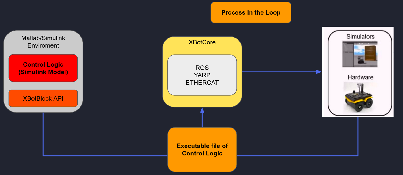
The process in the loop testing is a type of test where the user simply run the simulink model but this one is already codified and executed like external process. In this case no problem of ROS communication with XBotCore appear.
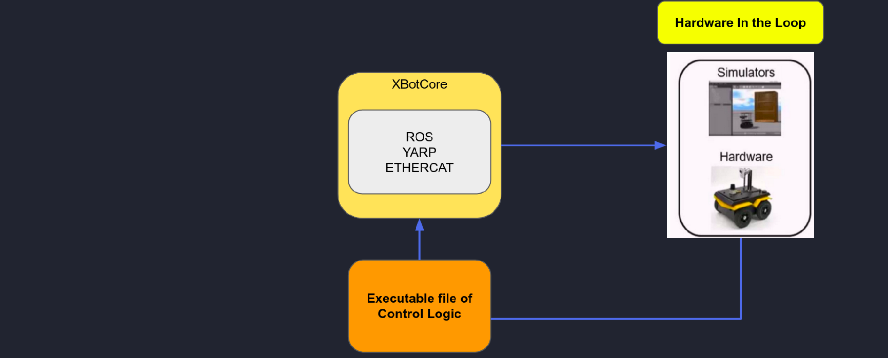
The hardware in the loop testing is the physical test on the real hardware where it’s possible to run non real time and real time code.
As already said the MIL testing is possible to perform it just pressing the play button of the simulink model, into Simulation Tab. Instead for the PIL and HIL the Robot tab should be used:
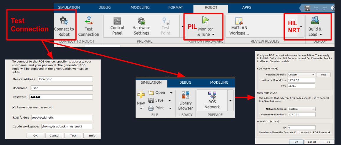
Process in the Loop
External mode enables Simulink on your host computer to communicate with the deployed model on your hardware board during runtime. It also provides an easy way to visualize the outputs of sources and show the effects of sink blocks in real-time.
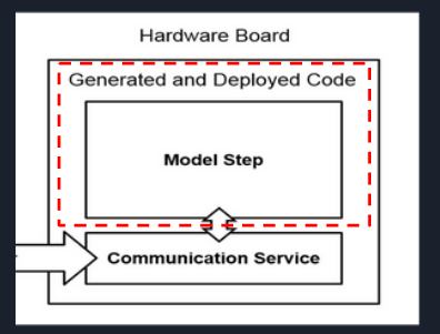
External mode creates a communication service on the host computer and hardware board. The two services establish a communication channel between the Simulink engine and generated code deployed on the hardware board. The communication service isolates the model process on the hardware board from the code and from the transport layer that formats, transmits, and receives the data packets. The communication service on the host computer receives the data packets through the transport layer and updates the Simulink model display. The diagram shows the connection that the external mode communication service creates between Simulink on the host computer and the deployed code on the hardware board.

Hardware in the Loop
Non Real Time Code (Standalone ROS node)
The code deployed and generated can be used like Non real time standalone node (binary file).
Real Time Code (XBotCore RT plugin)
The same code created can be reused inside the xbotcore real time plugin skeleton to create RT code (shared library).
